How to Calibrate A Quick Guide for MultiSport Calibration Tool
Description: This guide briefly goes over the new and improved calibration tool for MultiSport Arcade. It does not cover every nuance or situation but should help guide everyone to calibrate more easily.
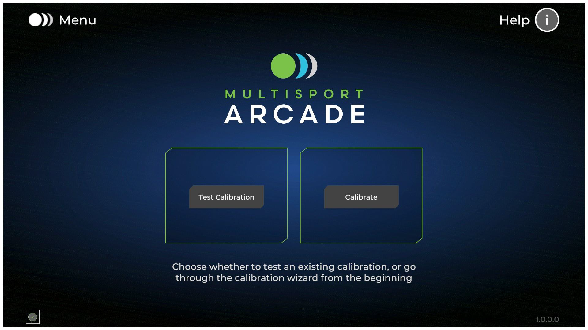
Main Menu
From this Screen, you have the option of Testing an Existing Calibration or Calibrating your System.
Note: Test Calibration will not exist for first time installs as the calibration file does not exist.
(We’ll introduce you to the Testing Screens at the end of Calibration)
Calibrate
To Calibrate select the Camera System you want to Calibrate.
A Dual Camera System is the only system we support at the moment.
The New Camera system will be announced and available at later dates, No ETA yet.
(Pro Tip: The version of software is always in the lower right corner)
Calibration starts, by making sure the environment is set up correctly.
Make sure the entire Projection is visible on the the Physical Screen
(Pro Tip: The white boarder that surrounds the projection of the tool should fit in the visible area of projection screen and not overlap any sides or canopy, if they do the projection may need adjusting.)
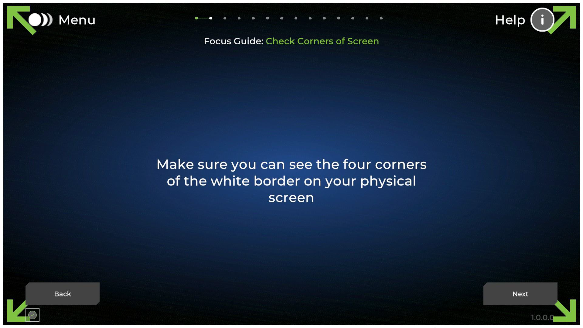
Focus Guide
On this screen, the image in the center should appear round, not oblong. Oblong will introduce errors in Launch Angle and/or Direction.
This important as many projection adjustment to make an image fit full screen will stretch causing the above issue.
(Pro Tip: There is Help on the upper right of every screen. Videos are going to be added over time).
You can use the Advanced Button to help understand the dimensions of the physical screen.
You want your Projected Image Aspect Ratio, to Match the Aspect Ratio of the Physical Screen to ensure the circle is round.
Now that our Environment is set up, it’s time to calibrate the cameras.
This Screen checks to make sure the cameras are connected, and we can communicate with them.
(Pro Tip: There is a little icon in the lower left, that can update you on any page…just mouse over for the message)
Camera Setup
Make sure the FrontView Camera is looking at the screen. Make sure BOTH cameras are right-side up (with the floor at the bottom of the Camera Feed)
Adjust Front View
This is a new Screen This screen is to help in AIMING the Front Facing Camera (the camera furthest from the screen).
Turn the Camera down, until the big green line disappears from the Camera Feed.
The unit itself needs to stay level, you are just adjusting the camera.
For installations outside of spec (8-10’ from Floor and Screen), may require some customization here.
(Note: Support does not recommend installing out of spec and we give best effort only when installed out side of spec.)
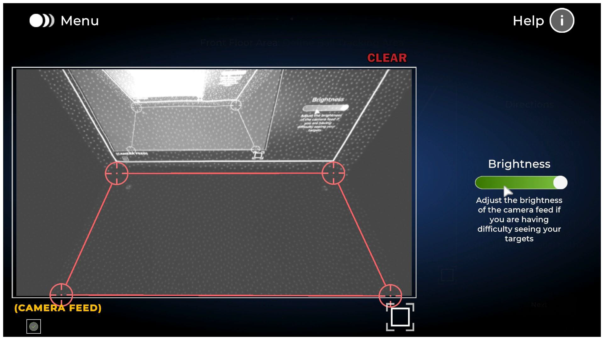
Front Floor Area:
Identify the Floor in front of the screen.
Start with the Markers near the screen.
Place a marker ON THE FLOOR that aligns with the White Border corner in the Projected Image For the bottom markers…try to maintain the same distance to the wall of the first markers placed.
The vertical lines should be parallel to the walls.
(Pro Tip: You can expand the screen with the icon at the bottom right of the Camera Feed)
(Pro Tip: Once Expanded, you can adjust the Brightness to see the booth in the Camera Feed even better)
Screen Boundary
Mark the boundaries of the projected image on the screen.
You should be able to see the White Outline, start with the corners of the White Outline, then follow the lines up for the top markers.
Screen To Floor
Measure the distance between the floor and the White Outline of the Projected Image on the Screen. Round the number up to a Whole Number.
Review Camera (Back Floor Play Area)
Marking the RearView Camera (You only have to do this once now)
Best Practice: Make sure the Tee Position is maybe 1/6th up from the bottom of the Camera Feed, or adjust the camera accordingly. (You really just don’t want the tee at the very bottom of the screen) In this window, outline the Tee Position. Give yourself a little room 2’ on any given side is plenty.
Tee Position
Now Mark the Tee Position.
Measure the distance between the tee and the scree and notate the distance in the Text Field.
NOTE: You no longer need to adjust the measurement. Just enter what you measured rounded to the nearest inch.
Clear Floor
Clear everything off the floor and get everything out of the Play Area.
THIS INCLUDES: Anyone performing the physical calibration (Installers or Customers).
When you hit next, a counter will start counting down from 10. During this time, several measurements are being made.
Test Calibration
You are now ready to TEST the calibration.
Note: It won’t be saved until you select SAVE AND EXIT in the lower Right.
2D Test Environment
Start with this 2D Test Environment.
Just throw a ball at the green circle in the center of the checkerboard.
Miss it?--that's Ok, you can just throw again!
Note where your ball hit the Screen The application will tell you where IT thinks the ball impacted the screen.
If the two are in the "ACCEPTABLE ZONE” you're fine.
If not…you can decide “how far off it is” and consider if you want to go back and redo the calibration.
REFINE CALIBRATION
You can also REFINE the calibration. Under REFINE CALIBRATION select START
Throw a ball at the green target. (No one is perfect, just get it in the checkerboard) The application will again tell you where it believes the ball struck the screen.
BUT NOW…with the mouse cursor, click where the ball actually impacted the screen.
You can do this over and over until you are satisfied. And if you miss the Checkerboard, don’t worry, just throw again. When satisfied Select DONE
This refine tool also replaces the calibration inside newer games such as QB, Pitching, Cornhole, ect. It is one Refinement for all.
This refine tool also replaces the calibration inside newer games such as QB, Pitching, Cornhole, ect. It is one Refinement for all.
(Pro Tip: On the Main Calibration Screen you can always RESET, and that will throw the Refinement out the window, like it never happened.
3D View
You also have the option of testing in the traditional 3D environment.
This is great for a bowling test, for example.
Nothing is Saved, until you select SAVE AND EXIT from the Main Test Calibration Page (2D Test Page)
Related Articles
MultiSport Arcade Calibration Tool Advanced Feature Guide
Description: This guide covers the use of the MultiSport Calibration Tools Advanced features. To be used Primarily by support and installers however customers can also use as needed to improve shot registration when standard calibration techniques do ...Crashing when hitting Ball (Calibration Tool and/or Game) on TruFlight 2
Symptom: The Calibration program, or E6 CONNECT crash immediately when hitting a ball. Resolution 1 : Run the program as an Administrator. This is the easiest, and the first thing to try Right Click on the Calibration tool and/or Game Icon Select ...How to Calibrate Apogee
Issue: Customers may report or request needing Assistance Calibrating Resolution: 1. Download and install AID (Apogee Intelligent Dashboard) from https://trugolf.com/support/ if you have not already. 2.Double click on the Apogee Shortcut Icon to ...MultiSport ARCADE: How to Calibrate the Lightgun
Symptoms: Crosshairs appear jittery and unresponsive, unable to shoot targets in games. NOTE: The Crosshair is never completely steady, as the camera always detect movement of the human body when held in hand. You can demonstrate this by placing the ...Apogee no laser
Issue: Users may report they are getting no active laser on the turf when either trying to calibrate or during play in E6Connect. A laser may not show during any phase of calibration or at the final stage at the end of Calibration (during Take A ...